
Resilient Modulus Test
Overview
The Resilient Modulus (Mr) is a fundamental property of materials, defined as the ratio between applied axial deviator stress and axial recoverable, or resilient
, strain (as shown in Eq. 1).
(Eq. 1) Mr = Stress / Strain (for rapidly applied loads)
The Resilient Modulus can be used to characterize unbound pavement materials (also known as subgrade material, which is material that is prepared and compacted before the placement of sub-base and/or base layers) and measure the material’s stiffness. Through the resilient modulus test, the stiffness of a material under various conditions, such as moisture content, density, and different stresses, can be adequately analyzed. The resilient modulus is actually an estimation of the material’s modulus of elasticity (E). However, while the modulus E is measured using slowly applied loads, the resilient modulus is measured using rapidly applied loads, like those experienced by pavements.
Performing the Resilient Modulus Test on a material provides a basic relationship between the applied stress and measured deformation of the material, which allows for a structural analysis of layered pavement systems. This test also allows pavement construction materials, including subgrade soils, to be characterized under various conditions and stress states, which can simulate conditions of a pavement that is subjected to traffic loads.
How is a Resilient Modulus Test Performed on Asphalt?
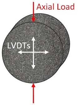
The Resilient Modulus Test, put simply, is a modified version of the indirect tension test, where a repeated vertical stress of a fixed magnitude, load duration and cyclic duration is applied to a cylindrical testing specimen. During each load cycle, the vertical stress is applied and removed in a sinusoidal fashion, resulting in a smooth application of the stress. The test specimen is subjected to many of these load cycles in order to accurately simulate traffic loading. The vertical load is applied to the side of a cylindrical specimen rather than to the face of a specimen, as is the case in most other tests. During the test, the resilient (recoverable) deformation of the specimen should be measured in the vertical and horizontal directions during each stress application. The diagram below shows the placement of the LVDTs that are used to measure the deformation of the specimen and shows where the load will be applied.
What does a Resilient Modulus Test Specimen Look Like?
For the Resilient Modulus Test, typical specimens are cylindrical in shape. These specimens should be either 101.6 ± 3.8 mm (4 in.) or 152.4 ± 9 mm (6 in.) in diameter and between 38.1 mm (1.5 in.) and 63.5 mm (2.5 in.) in thickness.
Test specimens are usually obtained from field coring by using a coring machine, created by the Marshall Compaction Method, or created by a gyratory compactor. Regardless of how the specimen is created, the faces of the specimen should be completely smooth and parallel, which can be done using a grinder and saw.
How are Specimen Characteristics Determined?
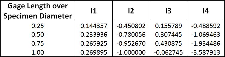
After performing the test, Poisson’s ratio can be determined for the specimen using the equation presented below. This calculation is based on the ratio of the length of the displacement gage to the diameter of the specimen, so the table provided must be used for the calculation of Poisson’s ratio.
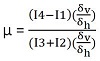
In the above equation, Poisson’s ratio is represented by μ, the recoverable vertical strain is represented by δv and the recoverable horizontal strain is represented by δh. Poisson’s ratio can be calculated using the instantaneous deformations or the total deformations. When observing the strain versus time graph for the specimen, a peak deformation will occur, followed by a linear recovery, then a curved recovery. The instantaneous recoverable deformation is equal to the deformation recovered during the linear portion of the recovery and the total recoverable deformation is equal to the total deformation recovery from the peak deformation until the next cycle begins. Poisson’s ratio can then be used to calculate the Resilient Modulus by using the following equation.
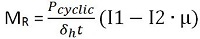
In the above equation, MR represents the Resilient Modulus, Pcyclic represents the cyclic axial load applied to the specimen, and t represents the thickness of the specimen. The values for I1 and I2 are the same values as used to calculate Poisson’s ratio. Depending on which Poisson’s ratio is used to calculate the Resilient Modulus (instantaneous or total), either the intantaneous Resilient Modulus or the total Resilient Modulus can be calculated.
Instantaneous Resilient Modulus: calculated using the instantaneous recoverable deformation that arises during the unloading portion of one load-unload cycle.
Total Resilient Modulus: calculated using the total recoverable deformation, which includes both the instantaneous recoverable and the time-dependent continuing recoverable deformation during the unload or rest-period portion of one cycle.
Keywords: Resilient Modulus — Elastic Modulus (E*) — Subgrade Material — Material Stiffness — Poisson’s Ratio — Material Characterization — Instantaneous Resilient Modulus — Total Resilient Modulus — Resilient Modulus Testing Equipment — Resilient Modulus Test
© 2016 Geotechnical Consulting and Testing Systems, LLC. All Rights Reserved.
- ASTM D4123 - Indirect Tension Test for Resilient Modulus of Bituminous Mixtures
- ASTM D7369 - Resilient Modulus of Bituminous Mixtures Test Standard
- AASHTO T274 - Resilient Modulus of Unbound Granular Base/Subase Materials and Subgrade Soils
- AASHTO TP31 - Resilient Modulus of Bituminous Mixtures by Indirect Tension
- AASHTO TP46 - Resilient Modulus of Soils and Aggregate Materials
- AASHTO T307 - Resilient Modulus of Soils Test Standard
- SHRP P07 - Creep Compliance, Resilient Modulus and Strength of Asphalt Materials
- NCHRP 1-28 - Determination of Resilient Modulus for Flexible Pavement Design